AI Robotics & Autonomous Systems — Beginner
Build a smart rover that senses obstacles and steers away—step by step.
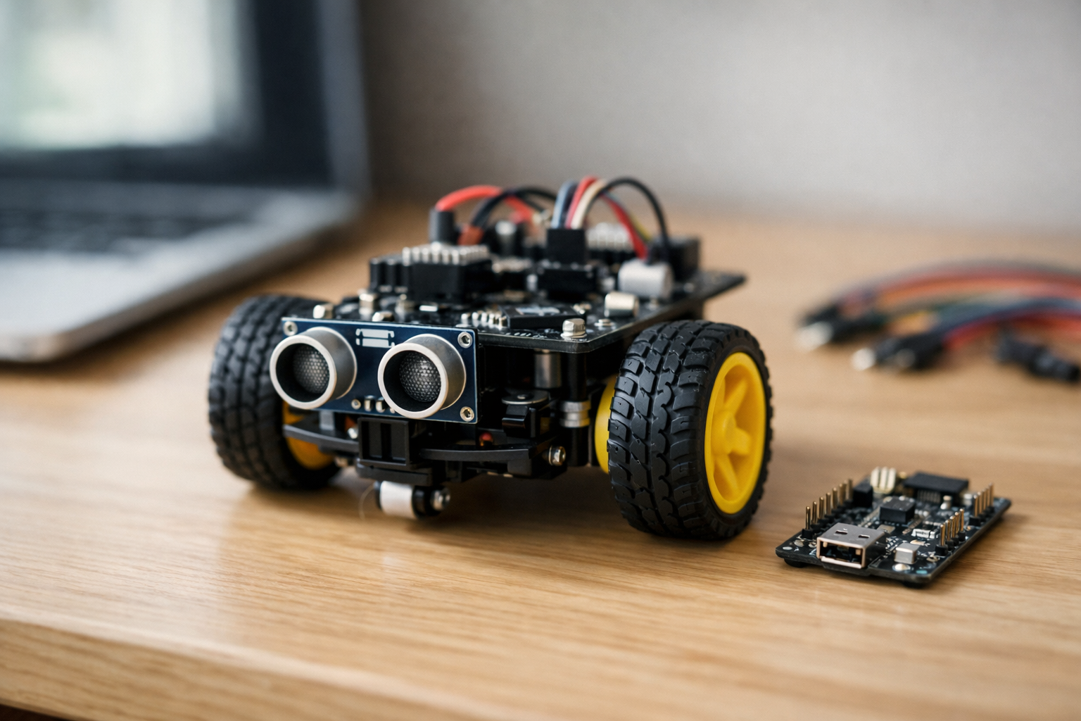
This beginner course is a short, book-style path to your first working autonomous rover: a small robot car that detects obstacles and steers away before it crashes. You do not need any previous experience in AI, robotics, electronics, or programming. We start from first principles, explain every part in plain language, and build confidence through small tests that always have a clear pass/fail result.
You’ll learn how a robot “thinks” at a basic level: it senses the world, makes a simple decision, then acts through motors. In this course, “AI” means practical decision-making logic you can understand and change—not complicated math. By the end, you’ll have a rover that drives forward, measures distance in front of it, and reacts consistently when something gets too close.
Your final project is an obstacle-avoiding rover that:
Many robotics tutorials jump straight into wiring diagrams or long code files. This course does the opposite: each chapter adds one new building block, then immediately tests it. You’ll never have to guess whether your problem is hardware, power, wiring, or code—because you’ll learn a simple troubleshooting routine that narrows the cause quickly.
The chapters progress like a short technical book:
This course is for absolute beginners: students, career changers, educators, and curious builders who want to understand AI robotics by doing. If you’ve ever wanted to build a robot but felt overwhelmed by the tools or terminology, this course is designed to remove that friction and give you a clear path to success.
You can follow the learning using the explanations alone, but to build the rover you’ll need a small set of common maker parts (a simple rover chassis with two DC motors, a controller board, a motor driver, a distance sensor, wires, and a battery). We focus on widely available components and teach the ideas in a way that transfers to other kits.
When you finish, you’ll have more than a robot—you’ll have a repeatable process for building autonomous projects:
If you’re ready to build your first autonomous rover, you can begin now. Register free to access the course, or browse all courses to compare learning paths on robotics and AI.
Robotics Engineer & Embedded AI Instructor
Sofia Chen designs small autonomous robots that combine simple sensors with practical decision-making logic. She has taught beginners how to wire electronics safely, write their first control programs, and turn prototypes into reliable, repeatable builds.
This course is about building a small rover that can drive around your home and avoid bumping into things. That goal is deliberately modest: you are not trying to solve “general intelligence,” you are learning how real robotics systems are assembled, tested, and improved. A beginner-friendly rover still forces you to think like an engineer—about power, wiring, sensing, timing, and the messy reality of noisy measurements and slipping wheels.
In this chapter you will define what “success” looks like for the rover and for each subsystem. You will also build a mental map of the full system—sensors feeding a controller, the controller making decisions, and motors executing those decisions through a motor driver. That map will guide your wiring, your first code tests, and your troubleshooting. By the end, you should be able to point to every major building block and explain why it’s there, how it connects, and how you will verify it works before moving on.
Robotics projects fail most often not because the idea is hard, but because the build is rushed: wires are swapped, grounds are forgotten, the battery is under-rated, or parts are tested only after everything is assembled. We’ll avoid that by working in small, testable steps and defining checkpoints you can pass one at a time.
Practice note for Define the goal: an obstacle-avoiding rover you can build at home: document your objective, define a measurable success check, and run a small experiment before scaling. Capture what changed, why it changed, and what you would test next. This discipline improves reliability and makes your learning transferable to future projects.
Practice note for Map the rover system: sensors → decisions → motors: document your objective, define a measurable success check, and run a small experiment before scaling. Capture what changed, why it changed, and what you would test next. This discipline improves reliability and makes your learning transferable to future projects.
Practice note for Identify parts: controller, motor driver, power, and distance sensor: document your objective, define a measurable success check, and run a small experiment before scaling. Capture what changed, why it changed, and what you would test next. This discipline improves reliability and makes your learning transferable to future projects.
Practice note for Set up your workspace: tools, safety, and a simple build plan: document your objective, define a measurable success check, and run a small experiment before scaling. Capture what changed, why it changed, and what you would test next. This discipline improves reliability and makes your learning transferable to future projects.
Practice note for Plan your first test: what “success” looks like for each part: document your objective, define a measurable success check, and run a small experiment before scaling. Capture what changed, why it changed, and what you would test next. This discipline improves reliability and makes your learning transferable to future projects.
Practice note for Define the goal: an obstacle-avoiding rover you can build at home: document your objective, define a measurable success check, and run a small experiment before scaling. Capture what changed, why it changed, and what you would test next. This discipline improves reliability and makes your learning transferable to future projects.
Practice note for Map the rover system: sensors → decisions → motors: document your objective, define a measurable success check, and run a small experiment before scaling. Capture what changed, why it changed, and what you would test next. This discipline improves reliability and makes your learning transferable to future projects.
Practice note for Identify parts: controller, motor driver, power, and distance sensor: document your objective, define a measurable success check, and run a small experiment before scaling. Capture what changed, why it changed, and what you would test next. This discipline improves reliability and makes your learning transferable to future projects.
Practice note for Set up your workspace: tools, safety, and a simple build plan: document your objective, define a measurable success check, and run a small experiment before scaling. Capture what changed, why it changed, and what you would test next. This discipline improves reliability and makes your learning transferable to future projects.
A robot is more than a gadget with moving parts. In practical terms, a robot is a system that (1) senses something about the world, (2) decides what to do next, and (3) acts on the world—repeatedly. If it only moves in a fixed pattern with no awareness, it’s closer to a toy mechanism. If it senses but never acts, it’s just an instrument. Robotics begins when sensing and action are connected through a controller that can change behavior based on conditions.
Your obstacle-avoiding rover is a perfect “minimum viable robot.” It will measure distance to objects in front of it, decide whether the path is clear, and command motors to drive forward or turn away. That’s enough to introduce the core engineering loop you’ll use in every robotics project: observe → decide → act → observe again.
Define the goal clearly so you can design for it. A realistic goal for a home-built rover is: “Drive forward on a flat floor, detect obstacles within a chosen threshold (for example 25–35 cm), stop, turn, and continue without frequent collisions.” Notice what’s not required: mapping your house, recognizing objects, or planning optimal routes. Limiting the goal is not “less ambitious”—it is how you build a system you can finish, understand, and improve.
Common beginner mistake: trying to “complete the rover” before proving each piece works. In robotics, a robot that moves unpredictably is harder to debug than separate parts on the bench. Treat the rover as a set of subsystems you will validate one at a time.
In this course, “AI” does not mean a large neural network running on a GPU. It means a robot making decisions from sensor data using rules you can explain and tune. This is sometimes called reactive control or rule-based autonomy. It is absolutely legitimate AI in the historical, practical sense: you are encoding a policy (what action to take) based on observations.
For obstacle avoidance, the simplest policy is a threshold rule: if the measured distance is greater than a safe distance, drive forward; otherwise stop and turn. You can extend that policy with a few practical refinements: slow down as you approach an obstacle, back up briefly if you get too close, or alternate left/right turns to avoid spinning in place.
Engineering judgment matters here because sensors are imperfect. A single “bad” reading might say an obstacle is 5 cm away when the real distance is 60 cm. If your logic reacts instantly to every reading, the rover will jitter, stop for no reason, or oscillate between forward and turn. You’ll learn to handle this by smoothing measurements (for example, taking the median of several readings) and by adding small timing rules (for example, “commit to turning for 400 ms before re-checking”).
The practical outcome: you should be able to describe your rover’s behavior in plain language and then implement it as a small set of rules. If you can’t explain it simply, it will be difficult to debug.
Think of your rover as a loop. Inputs are what the rover measures: distance readings from a sensor, perhaps later wheel speed or battery voltage. Outputs are what the rover commands: motor direction (forward/reverse) and motor speed (how fast). The controller sits between them and runs the loop many times per second.
Feedback is what makes the loop meaningful. When the rover drives forward, the distance to an obstacle should change. The next sensor reading tells the controller whether its last action improved the situation (path still clear) or made it worse (getting too close). Even without fancy math, this is feedback control: actions change the world; new measurements inform new actions.
Two ideas will save you hours of troubleshooting:
Noisy readings are normal. Ultrasonic and IR distance sensors can spike due to angles, soft surfaces, or electrical noise from motors. A practical approach is to take multiple readings and combine them: average for general smoothing, or median to reject outliers. Another simple technique is a “deadband”: ignore tiny changes in distance that shouldn’t affect behavior.
Your first mental model should be: sensor reading → cleaned/filtered value → decision rule → motor commands → new sensor reading. If the rover behaves oddly, identify which arrow in that chain is broken.
You can build an obstacle-avoiding rover with a small set of parts. Each part has a job, and mixing up those jobs is a common beginner error. Here is the system map: the distance sensor provides the input, the controller computes decisions, the motor driver turns low-power control signals into high-power motor current, the motors produce motion, and the battery provides energy for everything.
Controller (microcontroller board): This is the rover’s “brain” in the practical sense. It runs your program, reads the sensor, and outputs control signals (usually digital direction pins plus PWM for speed). Choose a board with enough I/O pins and good library support for your sensor.
Motor driver: Motors draw far more current than a microcontroller pin can provide. A motor driver (H-bridge module) lets the controller command direction and speed while the driver handles the motor current. Many driving issues trace back to wiring here: missing common ground, swapped motor leads, or insufficient current rating.
Power (battery pack + regulation): Motors can cause voltage dips and electrical noise. If the controller resets when motors start, suspect power first. Use a battery chemistry and voltage appropriate for your motors and driver, and consider separating motor power from logic power (or at least decoupling with capacitors) depending on your hardware.
Distance sensor: This is the rover’s “eyes.” Mounting matters as much as wiring. A sensor too low can see chair legs but miss table edges; too high can miss low obstacles. Point it straight ahead and keep it rigid so your readings are consistent.
Chassis, wheels, and motors: Mechanical reality matters. Unequal friction, misaligned wheels, and weak gearmotors cause curved driving even with perfect code. Expect to compensate with calibration (slightly different speeds left vs. right) and choose wheels with decent grip.
A simple build plan is: mount motors and wheels, mount the sensor with a clear forward view, mount the controller and motor driver where wires can reach, then wire power and signal lines cleanly. Label wires early; it’s faster than guessing later.
Small rovers still have enough power to burn components, melt insulation, or damage batteries if mishandled. Good safety habits also improve reliability, because most “mystery bugs” in early robotics are actually wiring or power faults.
Batteries: Treat battery packs with respect. Never short the terminals. Use a proper holder or connector; avoid loose metal parts on your bench. If using Li-ion/LiPo packs, use a charger designed for that chemistry and do not leave charging unattended. If a pack becomes hot, swells, smells odd, or shows physical damage, stop using it.
Heat and current: Motor drivers can overheat if stalled motors draw high current (for example, wheels blocked against a wall). During early tests, lift the rover so wheels can spin freely and keep test runs short. Touch-test carefully: if the driver is too hot to keep a finger on, you are near or beyond safe limits.
Short circuits and wiring discipline: Always power off before changing wiring. Check polarity twice before connecting power. A single reversed power connection can destroy a controller or sensor instantly. Use color conventions (red = positive, black = ground) and keep wiring tidy to avoid accidental contact.
Common ground: One of the most common mistakes is forgetting that the controller and motor driver must share ground for the control signals to be interpreted correctly. Even when motor power is separate, the grounds typically must be connected.
Workspace setup: Work on a non-conductive surface, keep a small screwdriver and wire cutters/strippers nearby, and have a way to quickly disconnect power (an inline switch or easily accessible connector). Practical outcome: you should be able to power the system on and off predictably, without sparks, heat spikes, or “random resets.”
Robotics is easier when you define checkpoints—small tests that prove one capability at a time. Your first chapter goal is not “a fully autonomous rover.” It is a clear roadmap and a plan for the first tests. Each checkpoint should have an observable success condition so you know when to proceed.
Define “success” before you test. For example: “At 30 cm threshold, the rover stops within 10 cm of a wall at least 8 out of 10 approaches.” That gives you something to tune: threshold distance, speed, turn time, and filtering strength.
Expect iteration. A rover that avoids obstacles but gets stuck in corners needs a different turn strategy. A rover that jitters needs better filtering or a longer decision interval. The practical habit you are building is to change one variable at a time, re-test, and keep notes. That is how you turn a pile of parts into a system you can trust.
1. What is the main learning goal of building the obstacle-avoiding rover in this course?
2. Which system map best describes how the rover works end-to-end in Chapter 1?
3. Why does Chapter 1 stress defining “success” for each subsystem before fully assembling the rover?
4. Which situation best matches the chapter’s examples of why rushed builds fail?
5. What does “thinking like an engineer” mean in the context of this beginner rover project?
In Chapter 1 you learned the “roles” in a rover: a controller makes decisions, motors create motion, and sensors report what the world looks like. In this chapter you will build the physical foundation that makes the later AI behavior possible: stable power, predictable wiring, and hardware that survives repeated testing. A beginner rover usually fails for simple reasons—reversed polarity, loose grounds, a motor drawing more current than expected, or a sensor cable picking up electrical noise. The goal is not perfection; the goal is a setup you can trust, reproduce, and debug without guessing.
We’ll treat your rover like an engineering system. First, choose a safe power approach and understand what “voltage” and “current” mean in practice. Then assemble the chassis and mount the motors and wheels so the robot can drive straight. Next, wire the motor driver and confirm the motors spin in both directions under code control. After that, connect the distance sensor and verify stable readings (including basic noise-handling). Finally, you’ll arrange the wiring into a repeatable layout—so future changes don’t turn into chaos.
Take your time here. Reliable hardware setup is what makes obstacle avoidance feel “smart” instead of random.
Practice note for Choose a safe power approach and understand voltage basics: document your objective, define a measurable success check, and run a small experiment before scaling. Capture what changed, why it changed, and what you would test next. This discipline improves reliability and makes your learning transferable to future projects.
Practice note for Assemble the chassis and mount motors and wheels: document your objective, define a measurable success check, and run a small experiment before scaling. Capture what changed, why it changed, and what you would test next. This discipline improves reliability and makes your learning transferable to future projects.
Practice note for Wire the motor driver and confirm the motors spin: document your objective, define a measurable success check, and run a small experiment before scaling. Capture what changed, why it changed, and what you would test next. This discipline improves reliability and makes your learning transferable to future projects.
Practice note for Connect the sensor and verify stable readings: document your objective, define a measurable success check, and run a small experiment before scaling. Capture what changed, why it changed, and what you would test next. This discipline improves reliability and makes your learning transferable to future projects.
Practice note for Create a repeatable wiring layout you can debug later: document your objective, define a measurable success check, and run a small experiment before scaling. Capture what changed, why it changed, and what you would test next. This discipline improves reliability and makes your learning transferable to future projects.
Voltage is the “push” that drives electricity through a circuit; current is the flow that actually moves. A common beginner mistake is to treat voltage as the only important number (for example, “my battery is 7.4V, so I’m fine”). For robots, current is often the limiting factor because motors can demand sudden bursts—especially when starting from rest, turning, or when a wheel is briefly stuck.
DC motors are “noisy” electrical loads because they are inductive devices with spinning brushes/commutators. When you switch a motor on and off (or drive it with PWM for speed control), the motor produces voltage spikes and electromagnetic interference (EMI). That noise can reset your microcontroller, corrupt sensor readings, or cause random behavior that looks like a software bug. When someone says, “my code works on USB power but fails on battery,” this is often the reason.
Practical implications for your rover build:
Engineering judgment: don’t aim for “perfectly quiet power,” aim for “quiet enough” that readings are stable and resets disappear. You will know you’re improving things when your rover behaves the same way every run, not only on the bench but also on the floor with wheels installed.
A safe power approach starts with choosing a battery chemistry and a regulation plan that matches your controller and motors. Many beginner rovers use a 2-cell Li-ion/LiPo pack (often called “2S,” nominally ~7.4V) for motors, plus a regulated 5V (or 3.3V) rail for the microcontroller and sensors. The key idea: motors want current and tolerate some voltage variation; microcontrollers want a clean, stable voltage.
What you typically need:
What to avoid (common beginner traps):
Workflow recommendation: assemble the chassis and mount the motors and wheels before finalizing cable lengths. Mechanical build influences wiring: motor leads must reach the driver without tension, and the battery must be mounted so it won’t shift and pull on connectors when the rover accelerates or bumps into obstacles.
Your microcontroller cannot drive DC motors directly; it lacks the current capability and cannot handle the back-EMF noise. A motor driver (often an H-bridge module) acts as a power interface: the controller provides small logic signals, and the driver switches battery power to the motors safely. Most beginner drivers expose two categories of control signals per motor: direction and speed.
Direction pins select which way current flows through the motor. Many drivers use two inputs (for example IN1/IN2). A typical pattern is:
Speed pins are usually PWM-capable inputs (sometimes called ENA/ENB or “enable”). PWM rapidly switches power on and off; the motor’s inertia averages it into a controllable speed. Your first goal is not perfect speed control—it’s verification: confirm each motor spins, confirm direction matches your “forward” definition, and confirm PWM changes speed.
Practical wiring and test steps:
Engineering judgment: pick a “forward” convention early (e.g., both wheels pushing the rover straight ahead) and stick to it. Label left motor and right motor connections at the driver. This discipline prevents later confusion when obstacle avoidance seems to turn the wrong way.
A repeatable wiring layout is a debugging tool. Messy wiring creates intermittent faults that look like random sensor noise or “bad code.” Your objective is to make the electrical system understandable at a glance: where power enters, where it splits to motor power and logic power, where signals travel, and where grounds return.
Three habits make the biggest difference:
Routing tips for reliability:
Common mistake: building a “rats’ nest” that works on the table, then fails once you mount everything to the chassis. Do your final wiring with the chassis assembled, wheels installed, and battery mounted. Then pick up the rover and gently shake it—nothing should tug or unplug. This is the difference between a one-time demo and a rover you can iteratively improve.
Obstacle avoidance depends on distance measurements that are not only “correct,” but also consistent. Many distance sensors (especially ultrasonic modules) are sensitive to mounting angle, vibration, and nearby surfaces. Even time-of-flight sensors can be affected by shiny targets and crosstalk if mounted poorly. Before you write clever logic, mount the sensor so it sees what the rover will hit.
Mounting guidelines that improve measurement stability:
After mounting, verify stable readings before integrating motor motion. Read distance while the rover is stationary, then while motors spin with wheels off the ground. If readings become erratic during motor PWM, you are seeing electrical noise coupling into the sensor. Solutions include better routing (Section 2.4), ensuring a solid ground, and adding decoupling capacitors where appropriate (often already present on modules).
Practical outcome: you want distance readings that change smoothly as you move a box closer and farther. Some jitter is normal; your later code can handle it with simple filtering (for example, median-of-3 readings or rejecting sudden impossible jumps). But no code can rescue a sensor that is pointed at the floor or vibrating wildly.
Before you attempt full obstacle avoidance, run a “smoke test”: a short, repeatable checklist that catches the most common wiring and power mistakes early. The rule is simple: validate one subsystem at a time, from power → controller → motor driver → motors → sensor. If you change wiring, rerun the checklist. This habit saves hours.
When this checklist passes, you have a reliable platform: the rover is powered safely, the driver responds predictably, the motors can be controlled in speed and direction, and the sensor data is stable enough to use. That reliability is what makes the next chapters fun—you’ll be able to focus on decision rules, tuning, and behavior rather than chasing intermittent hardware ghosts.
1. What is the main purpose of focusing on power and wiring in Chapter 2?
2. Which situation best matches the kind of beginner failure Chapter 2 aims to prevent?
3. After wiring the motor driver, what is the most meaningful verification step described?
4. When connecting the distance sensor, what outcome indicates the setup is ready for later behavior work?
5. Why does Chapter 2 emphasize creating a repeatable wiring layout?
This chapter is where your rover stops being “a wiring project” and becomes a real robot: it senses something in the world, makes a decision, and moves. The key is to work in small, testable steps. First you confirm your controller can accept code. Then you read distance data and learn what “noisy” looks like. Next you drive the motors in a controlled way (forward, stop, turn) and verify direction and speed. Finally, you combine sensing and motion in a short routine that logs what happened so you can fix problems early without guessing.
Begin with an engineering mindset: treat every new capability like a lab experiment. Change one thing at a time, keep tests short, and write down what you observed. A rover that “kind of works” is usually a rover with untested assumptions—wrong pin numbers, reversed motor leads, unstable power, or a sensor that occasionally returns nonsense. Your goal here is not a perfect obstacle avoider yet; it’s building reliable building blocks you can trust in Chapter 4.
Throughout the chapter, keep safety in mind. When testing motors, lift the wheels off the table or set the rover on a stand. Use a low speed at first. Keep a finger near the power switch (or battery connector) so you can cut power instantly if something behaves unexpectedly.
Practice note for Install the coding tools and connect your controller: document your objective, define a measurable success check, and run a small experiment before scaling. Capture what changed, why it changed, and what you would test next. This discipline improves reliability and makes your learning transferable to future projects.
Practice note for Write a tiny program to read distance data: document your objective, define a measurable success check, and run a small experiment before scaling. Capture what changed, why it changed, and what you would test next. This discipline improves reliability and makes your learning transferable to future projects.
Practice note for Write a tiny program to drive forward, stop, and turn: document your objective, define a measurable success check, and run a small experiment before scaling. Capture what changed, why it changed, and what you would test next. This discipline improves reliability and makes your learning transferable to future projects.
Practice note for Combine reading + moving in a controlled test routine: document your objective, define a measurable success check, and run a small experiment before scaling. Capture what changed, why it changed, and what you would test next. This discipline improves reliability and makes your learning transferable to future projects.
Practice note for Log results and spot problems early (without guessing): document your objective, define a measurable success check, and run a small experiment before scaling. Capture what changed, why it changed, and what you would test next. This discipline improves reliability and makes your learning transferable to future projects.
Practice note for Install the coding tools and connect your controller: document your objective, define a measurable success check, and run a small experiment before scaling. Capture what changed, why it changed, and what you would test next. This discipline improves reliability and makes your learning transferable to future projects.
Practice note for Write a tiny program to read distance data: document your objective, define a measurable success check, and run a small experiment before scaling. Capture what changed, why it changed, and what you would test next. This discipline improves reliability and makes your learning transferable to future projects.
Practice note for Write a tiny program to drive forward, stop, and turn: document your objective, define a measurable success check, and run a small experiment before scaling. Capture what changed, why it changed, and what you would test next. This discipline improves reliability and makes your learning transferable to future projects.
Practice note for Combine reading + moving in a controlled test routine: document your objective, define a measurable success check, and run a small experiment before scaling. Capture what changed, why it changed, and what you would test next. This discipline improves reliability and makes your learning transferable to future projects.
Robot code is simply a set of instructions your controller executes, but it runs in a world that keeps changing. That’s why most robot programs follow a “read–decide–act” loop: read sensors, decide what to do, then command the motors. On microcontrollers (Arduino-style), you usually see two main parts: a one-time setup (configure pins, start serial logging) and a repeating loop (do the work again and again).
Variables are named containers for values you care about: distance in centimeters, motor speed, or a threshold like stopDistanceCm. Using variables is not just for convenience—it’s a tuning tool. If your rover stops too late, you adjust a threshold variable rather than rewriting logic all over your code.
Loops matter because sensors are noisy and motors have inertia. A single sensor reading may be wrong, and a single motor command may not produce the exact movement you expect. In practice, you will: (1) sample distance multiple times, (2) compute a stable value (like a median), and (3) only then decide to drive forward or turn.
Common beginner mistake: writing code that blocks for a long time (for example, huge delays) so the rover “goes blind” while moving. Short delays are fine for early testing, but develop the habit of thinking in cycles: “How often do I update the sensor? How quickly can I stop?” Practical outcome: by the end of this chapter you will have a loop that reads distance, prints it, moves briefly, then repeats—small steps you can observe and trust.
Before you involve motors and sensors, confirm your development tools and connection are solid. Install your controller’s IDE (for example, Arduino IDE) and any required board package. Use a known-good USB cable—many “charging cables” cannot transfer data, and that single detail can waste hours.
Connect the controller to your computer and select the correct board and port in the IDE. Upload a minimal “blink” or “hello serial” program. The goal is not the LED; the goal is verifying the entire toolchain: compile → upload → run. Then open the Serial Monitor and print a line like “boot ok” once in setup and a counter in loop. If the counter increments steadily, your loop is running.
Engineering judgement: if uploads sometimes fail, don’t ignore it and move on to motors. Intermittent connection issues often become “random robot behavior” later because resets happen when power droops or cables wiggle. Fix the foundation first.
Common mistakes include selecting the wrong COM port, leaving another program (like a serial terminal) holding the port open, or powering the motors from the board’s USB 5V line. Practical outcome: you end this section with a repeatable process—plug in, choose port, upload, open serial—and you can prove the board is alive with text output, not guesswork.
An ultrasonic distance sensor works by sending a short sound pulse (trigger) and measuring how long it takes to hear the echo return. Your code converts time-of-flight into distance. Conceptually: distance = (speed of sound × time) / 2. The “/2” is because the pulse travels to the obstacle and back.
In code, you set the TRIG pin high briefly (often 10 microseconds), then measure the width of the ECHO pulse in microseconds. Many beginner libraries wrap this, but it’s valuable to understand what’s happening so you can diagnose bad readings. If your echo time is zero, your wiring or pin mode is likely wrong. If the time is huge, you may be measuring noise or missing the timeout.
Noisy readings are normal. Soft materials, angled surfaces, or tight corners can cause inconsistent echoes. Practical technique: take 5 readings, discard obvious outliers, and use the median (more robust than an average). Also enforce limits: if the computed distance is below a physically impossible minimum (like 1 cm) or above the sensor’s max range, treat it as “no valid reading” and keep the previous good value.
Log everything. Print the raw echo time and the converted centimeters. When you wave your hand closer and farther, you should see the numbers respond smoothly most of the time. If values jump randomly, check power stability and ground connections—ultrasonic sensors can behave strangely when the supply is noisy. Practical outcome: you will have a small program that repeatedly prints distance measurements you can trust enough to base movement decisions on.
DC motors need two kinds of control: direction and speed. Direction is typically set by an H-bridge motor driver using two logic inputs per motor (often called IN1/IN2). Speed is usually controlled by PWM (pulse-width modulation) on an enable pin (EN) or a dedicated PWM input. PWM does not “lower voltage” in a smooth analog way; instead it rapidly switches power on and off. The motor averages that power mechanically, producing a lower effective speed.
Start by separating concerns: first verify direction with a very low speed (or a short burst), then work on speed. If your rover drives backward when you command forward, you can fix it in two ways: swap the motor leads (hardware fix) or invert the logic in code (software fix). Choose one and document it so you don’t “fix it twice” later.
Engineering judgement: avoid powering motors from the controller’s 5V regulator. Motors create voltage dips and electrical noise that can reset your controller and corrupt sensor readings. Use a proper battery pack for the motor driver and share a common ground between the driver and controller so logic signals have a reference.
Common mistakes: forgetting common ground, using non-PWM pins for speed control, or setting both direction pins high/low in a way that activates braking unintentionally. Practical outcome: you will know which pins set direction, which pin sets speed, and you’ll be able to command each wheel independently—critical for reliable turning and obstacle avoidance.
Before you attempt obstacle avoidance, write tiny “test scripts” that move in predictable patterns. This is your controlled test routine: command forward for one second, stop for one second, turn left for half a second, stop, then turn right. Keep speeds low enough that the rover won’t launch itself off your desk. If possible, lift the drive wheels or place the rover on blocks for the very first run.
Implement movement as small functions such as driveForward(speed), turnLeft(speed), and stopMotors(). This structure prevents duplicated pin logic and makes your final behavior easier to read. Add serial prints like “FORWARD”, “STOP”, “TURN_LEFT” so you can correlate what the code thought it was doing with what the rover actually did.
Once basic movement works, combine reading + moving in a looped routine: read distance, print it, then move forward briefly if clear; otherwise stop and turn. For now, keep it deterministic: use a fixed turn time (e.g., 300–600 ms) so you can evaluate turning consistency. This isn’t “smart” yet—it’s testable.
Practical tuning tip: if the rover curves instead of going straight, your motors do not match perfectly. Calibrate by using slightly different PWM values for left and right until forward motion is straight on your floor. Write those values down. Practical outcome: you gain confidence that “forward means forward” and “turn means turn,” which prevents you from blaming the sensor when the real issue is motor control.
Robotics debugging is pattern matching: you observe a symptom, list the most likely causes, then run a quick check that isolates one variable. Avoid changing wiring, code, and power all at once. Instead, keep a simple checklist and collect evidence with logs.
Logging is your early-warning system. Print the distance, chosen action, and PWM values each loop. If something goes wrong, you can answer: “Did the sensor say obstacle?” “Did the code decide to stop?” “Did the motor command actually change?” Practical outcome: you finish the chapter with a repeatable troubleshooting workflow, so your rover improves through evidence and iteration instead of guesswork.
1. What is the main reason the chapter recommends working in small, testable steps?
2. After you successfully read distance data, what understanding are you expected to gain before moving on?
3. When testing motor movement (forward, stop, turn), what should you verify in a controlled way?
4. Which situation best matches the chapter’s idea of a rover that “kind of works” due to untested assumptions?
5. What safety practice does the chapter recommend during early motor tests?
In the previous chapters you built the hardware, read distance measurements, and proved you can spin motors in both directions. Now you’ll turn those pieces into behavior: the rover drives forward, notices something in its path, makes a decision, and recovers if it gets into trouble. This is the moment your rover stops being “a cart with motors” and starts acting like a simple autonomous system.
For beginners, the most reliable path is not to start with machine learning or complex mapping. Instead, you will build obstacle avoidance from small, inspectable rules. These rules may be simple, but they can still feel like “AI” because they turn perception (distance sensor readings) into action (motor commands) in a loop. The engineering work is choosing safe distances, dealing with noisy readings, and designing recovery moves so your rover doesn’t panic, oscillate, or wedge itself into corners.
This chapter walks you through a practical workflow: define a safe stopping distance and turning strategy, build the first obstacle-avoidance loop (drive, check, react), handle bad readings so the rover doesn’t overreact, add a “stuck” escape move for tight spaces, and finally test everything in a small course while recording what fails. Your goal is not perfection; your goal is repeatable behavior you can tune.
Practice note for Define a safe stopping distance and turning strategy: document your objective, define a measurable success check, and run a small experiment before scaling. Capture what changed, why it changed, and what you would test next. This discipline improves reliability and makes your learning transferable to future projects.
Practice note for Build the first obstacle-avoidance loop (drive, check, react): document your objective, define a measurable success check, and run a small experiment before scaling. Capture what changed, why it changed, and what you would test next. This discipline improves reliability and makes your learning transferable to future projects.
Practice note for Handle bad readings so the rover doesn’t panic: document your objective, define a measurable success check, and run a small experiment before scaling. Capture what changed, why it changed, and what you would test next. This discipline improves reliability and makes your learning transferable to future projects.
Practice note for Add a “stuck” escape move for corners and tight spaces: document your objective, define a measurable success check, and run a small experiment before scaling. Capture what changed, why it changed, and what you would test next. This discipline improves reliability and makes your learning transferable to future projects.
Practice note for Test in a small course and record what fails: document your objective, define a measurable success check, and run a small experiment before scaling. Capture what changed, why it changed, and what you would test next. This discipline improves reliability and makes your learning transferable to future projects.
Practice note for Define a safe stopping distance and turning strategy: document your objective, define a measurable success check, and run a small experiment before scaling. Capture what changed, why it changed, and what you would test next. This discipline improves reliability and makes your learning transferable to future projects.
Practice note for Build the first obstacle-avoidance loop (drive, check, react): document your objective, define a measurable success check, and run a small experiment before scaling. Capture what changed, why it changed, and what you would test next. This discipline improves reliability and makes your learning transferable to future projects.
Practice note for Handle bad readings so the rover doesn’t panic: document your objective, define a measurable success check, and run a small experiment before scaling. Capture what changed, why it changed, and what you would test next. This discipline improves reliability and makes your learning transferable to future projects.
Practice note for Add a “stuck” escape move for corners and tight spaces: document your objective, define a measurable success check, and run a small experiment before scaling. Capture what changed, why it changed, and what you would test next. This discipline improves reliability and makes your learning transferable to future projects.
When people hear “AI robot,” they often imagine a neural network. But for an obstacle-avoiding rover, decision rules are a legitimate, beginner-friendly form of AI: the robot senses the world, applies a policy (rules), and acts. If the rover consistently avoids collisions without your direct control, it is demonstrating autonomy—even if the “brain” is a handful of if/else statements.
A good rule set has two properties: it is inspectable (you can explain why the rover did what it did) and it is tunable (you can adjust distances, speeds, and timing). Start with the smallest useful behavior loop: drive forward, measure distance, and if the distance is below a threshold, stop and turn. This “drive, check, react” loop is your first obstacle-avoidance loop.
Common beginner mistake: writing rules that fight each other. For example, if you always command “forward” at the top of the loop and “turn” at the bottom, the rover may twitch because it receives conflicting commands every few milliseconds. Another mistake is skipping a true stop before turning. On many rovers, a brief stop (even 50–150 ms) reduces skid, gives the motor driver time to settle, and makes turns more consistent.
Practical outcome: by the end of this section, you should be able to describe your rover’s behavior as a small policy. If you can’t explain it in a few sentences, it’s too complicated to tune.
Obstacle avoidance lives or dies on thresholds. A single number like STOP_DISTANCE_CM seems simple, but choosing it requires engineering judgment. The correct stopping distance depends on speed, sensor placement, rover momentum, and the time it takes your loop to notice the obstacle and react.
Start by defining two distances, not one: a slowdown distance and a stop/turn distance. This creates hysteresis (a buffer) so the rover doesn’t “flutter” between forward and turn when it’s right on the edge.
How to pick initial numbers: measure your rover’s stopping behavior. Place a box in front of the rover, drive toward it at your intended speed, and estimate how far the rover travels after you command “stop.” Add extra margin for sensor jitter and loop delay. If your rover needs 10 cm to reliably stop, a 25 cm stop threshold is not “too cautious”—it’s safety.
Turning strategy also needs a threshold mindset. If you turn too early, the rover may wander and look indecisive. If you turn too late, it collides or grazes obstacles. Choose a consistent approach: when too close, stop, reverse briefly (optional), then turn for a fixed time. Fixed-time turns are crude but effective for beginners because they are predictable and easy to tune.
Common mistake: using the sensor’s maximum range as if it were reliable. Many distance sensors become noisy at long distances and unstable at very close distances. Your thresholds should live in the sensor’s “trusted zone,” where readings are repeatable. Practical outcome: you’ll have a documented set of distances and a clear turning plan that you can adjust without rewriting your whole program.
A simple rule like “if close, turn” works in open space, but it often fails in corners or narrow passages. The rover may repeatedly detect an obstacle, start turning, immediately see another obstacle, and thrash. A practical fix is to think in states: the rover is either driving normally, actively avoiding, or recovering from a stuck situation. This is a beginner-friendly version of a finite state machine.
Define three core states:
The key idea is commitment. In AVOID state, you don’t keep reconsidering every 10 ms. You commit to the maneuver long enough to matter—e.g., reverse for 200 ms, then turn right for 350 ms—then return to DRIVE and re-evaluate. That commitment prevents panic behavior caused by fast sensor fluctuations.
Now add a stuck detector. You can detect “stuck” without fancy sensors by using time and repetition: if you trigger avoidance too many times within a short window (for example, 3 avoid maneuvers in 5 seconds), you are likely in a corner or oscillating between two obstacles. In that case, switch to RECOVER: reverse longer, turn the opposite direction, or do a “wiggle” (short left-right turns) to break free.
Common mistakes: (1) never resetting the counter that tracks repeated avoid events, causing the rover to enter RECOVER forever; (2) choosing recovery moves that are too gentle to matter; and (3) reversing so long that you exit the course or hit something behind you. Practical outcome: your rover will feel calmer and more intentional, and you’ll have a clear place in your code to add improvements later.
Distance sensors do not report truth; they report measurements. Measurements include noise: random variation, occasional spikes, and sometimes “bad reads” (zeros, max range, or nonsense values). If your rover treats every reading as perfect, it will overreact. This is why beginners often see a rover that suddenly spins for no reason or stops in the middle of an open floor.
First, define what a “bad reading” looks like for your sensor. For many ultrasonic sensors, a reading of 0 cm or an extremely large value can indicate no echo or timing issues. For some time-of-flight sensors, you may get a validity flag. In code, treat invalid readings as unknown, not as “very close” and not as “very far.” A practical rule is: if the reading is invalid, reuse the last valid reading for one cycle, and if invalid persists, slow down or stop cautiously.
Second, smooth your data. You do not need advanced math. Two beginner methods work well:
filtered = 0.7*filtered + 0.3*new. This calms jitter but adds lag.Choose based on your behavior. If the rover “panics” from spikes, use median-of-3. If it jitters around a threshold, use EMA (and consider thresholds with hysteresis from Section 4.2). Beware of smoothing too much: heavy filtering can delay detection and cause late turns.
Common mistake: printing every raw sensor value at high speed while expecting smooth motion. Serial printing can slow your loop and change timing, and raw values will look scary. Instead, log filtered values at a lower rate (e.g., 5–10 times per second) and tune from there. Practical outcome: your rover will stop reacting to single bad measurements and will behave more consistently in real rooms with varied surfaces.
Obstacle avoidance is not only about logic; it’s about timing. Your rover lives in a loop, and everything you do inside that loop affects how quickly you can notice obstacles and respond. The classic beginner trap is using long delay() calls. While delaying, your code is “blind”—it is not reading sensors or updating decisions. That can make the rover crash even with good thresholds.
Some delays are useful, but they must be intentional. A short stop delay before turning can improve mechanical consistency. A fixed-time turn is itself a delay-like behavior. The problem is stacking long, blocking delays that prevent re-checking the world. A better pattern is to use time-based steps with millis(): start an action, remember when it started, and keep looping while you wait for the time to pass. This allows you to keep reading sensors, update counters, and—if needed—abort a maneuver.
Motor control also interacts with timing. If your motor driver uses PWM for speed, small speed changes can cause big behavior differences: at low PWM the rover may stall; at high PWM it may overshoot turns. When testing, pick two or three known-good speed settings (e.g., cruise, slow, turn) rather than continuously varying speed. This reduces tuning complexity.
Common mistakes: (1) turning for too long without checking distance again, causing spinning near obstacles; (2) putting sensor reads inside long motor routines; (3) changing PWM values constantly and then not knowing which change fixed (or broke) behavior. Practical outcome: you’ll understand why the rover sometimes behaves differently when you add debug prints or small delays, and you’ll have a timing strategy that supports reliable avoidance.
You can’t tune obstacle avoidance by “trying it a few times” in random conditions. You need a small course and fair trials so you can tell whether a change improved behavior or just got lucky. Build a repeatable test area on the floor: a start line, a few obstacles, and boundaries that keep the rover contained.
A simple course can be made from cardboard boxes, books, and painter’s tape. Include at least one straight corridor, one corner, and one open area. The goal is to expose failure modes: late stopping, oscillation near walls, and getting stuck in tight spaces.
Run fair trials like an engineer. Do 5–10 runs per code change. Start the rover from the same position and orientation each time. Record what fails: “hit obstacle,” “stuck oscillating,” “spun in place,” “escaped successfully,” and note the approximate sensor readings when the failure happened. If you can, capture short videos; they reveal patterns you won’t notice in the moment.
When a failure happens, resist the urge to add complicated rules immediately. First ask: is it a threshold problem, a noise problem, a timing problem, or a missing recovery behavior? For example, repeated back-and-forth turns in a corner usually indicates a need for state commitment (Section 4.3) or hysteresis (Section 4.2), not more random turning.
Practical outcome: you’ll finish this chapter with a tuning routine—test, measure, adjust, retest—and a rover that can complete a small course more consistently. You’ll also have a written list of failure modes to guide improvements in later chapters.
1. Why does Chapter 4 emphasize using small, inspectable rules instead of starting with machine learning or complex mapping?
2. Which sequence best describes the first obstacle-avoidance loop introduced in this chapter?
3. What is the main purpose of defining a safe stopping distance and a turning strategy before coding the behavior loop?
4. Why does the chapter include handling bad sensor readings as part of obstacle avoidance logic?
5. What problem does adding a “stuck” escape move primarily address?
Your rover works: it reads distance, drives forward, and turns away from obstacles. Now you’ll do the part that makes it feel “robotic” instead of “random”: calibration, tuning, and troubleshooting. Beginners often assume robots behave like code—deterministic and repeatable. Real robots behave like hardware—full of friction, slack, battery sag, sensor quirks, and small mismatches that add up over time. This chapter teaches you how to turn those messy realities into a stable, repeatable rover you can trust.
You will do five practical improvements: (1) calibrate turning so left and right are consistent, (2) tune speed for stability and better sensor response, (3) fix common power/reset issues, (4) improve obstacle detection through better placement and parameters, and (5) create a “known good” configuration you can restore anytime. The goal is not perfection; the goal is a rover that behaves consistently enough that future upgrades (like better navigation) are possible.
Work in a consistent test area (same surface, similar lighting, same battery state). If you change the floor, the battery, or the wheel alignment, you’ve changed the experiment. This chapter gives you workflows you can repeat any time your rover starts acting “weird.”
Practice note for Calibrate turning so left and right are consistent: document your objective, define a measurable success check, and run a small experiment before scaling. Capture what changed, why it changed, and what you would test next. This discipline improves reliability and makes your learning transferable to future projects.
Practice note for Tune speed for stability and better sensor response: document your objective, define a measurable success check, and run a small experiment before scaling. Capture what changed, why it changed, and what you would test next. This discipline improves reliability and makes your learning transferable to future projects.
Practice note for Fix common power and reset issues: document your objective, define a measurable success check, and run a small experiment before scaling. Capture what changed, why it changed, and what you would test next. This discipline improves reliability and makes your learning transferable to future projects.
Practice note for Improve obstacle detection with better placement and parameters: document your objective, define a measurable success check, and run a small experiment before scaling. Capture what changed, why it changed, and what you would test next. This discipline improves reliability and makes your learning transferable to future projects.
Practice note for Create a “known good” configuration you can restore anytime: document your objective, define a measurable success check, and run a small experiment before scaling. Capture what changed, why it changed, and what you would test next. This discipline improves reliability and makes your learning transferable to future projects.
Practice note for Calibrate turning so left and right are consistent: document your objective, define a measurable success check, and run a small experiment before scaling. Capture what changed, why it changed, and what you would test next. This discipline improves reliability and makes your learning transferable to future projects.
Practice note for Tune speed for stability and better sensor response: document your objective, define a measurable success check, and run a small experiment before scaling. Capture what changed, why it changed, and what you would test next. This discipline improves reliability and makes your learning transferable to future projects.
Practice note for Fix common power and reset issues: document your objective, define a measurable success check, and run a small experiment before scaling. Capture what changed, why it changed, and what you would test next. This discipline improves reliability and makes your learning transferable to future projects.
Practice note for Improve obstacle detection with better placement and parameters: document your objective, define a measurable success check, and run a small experiment before scaling. Capture what changed, why it changed, and what you would test next. This discipline improves reliability and makes your learning transferable to future projects.
If your rover doesn’t drive straight when you command “forward,” that is normal. Drift usually comes from three sources: friction differences, uneven weight distribution, and motor mismatch. Even two “identical” DC motors can produce different speeds at the same PWM value. One gearbox may be tighter, one wheel may have slightly different diameter, or one motor may have a different no-load speed.
Friction is not just the floor. It includes wheel wobble, axle alignment, caster wheel drag, and the motor driver’s internal voltage drop. Weight matters because the heavier side presses harder into the floor, increasing rolling resistance. If your battery pack sits to the left, the left wheel may slip less (or more) depending on the surface. That changes turning and straight-line tracking.
A common mistake is trying to “code away” drift by constantly correcting based on distance sensor readings. That usually makes things worse because the distance sensor is looking forward, not at wheel motion. Instead, treat drift as a calibration problem: first make the mechanical build reasonable (wheels tight, chassis not warped, wires not scraping the ground), then compensate for the remaining mismatch in software.
Expect drift to change with battery voltage. At lower voltage, one motor might “drop out” earlier than the other, increasing mismatch. That’s why you’ll calibrate using repeatable tests and record the battery condition you used.
Calibration means turning a vague command like “turn left” into a predictable action like “rotate about 90°.” Without wheel encoders, you’ll calibrate using time and careful measurement. The method is simple: set a fixed PWM (speed), run a turn for a fixed duration, and measure the resulting angle or how far the rover’s nose moved relative to a reference line.
Start with a marked test pad: use painter’s tape to create a starting box and a forward reference line. Place the rover so the front bumper touches the line. Command a timed pivot turn (left motor backward, right motor forward) for, say, 300 ms. After the turn, measure the angle using a phone angle app, a printed protractor, or a simple “square test”: after a nominal 90° turn, drive forward a short distance and see whether the path aligns with a taped perpendicular line.
Do this for both left and right turns. If left turns are consistently stronger, don’t immediately change everything—add a calibration factor. Typical approaches include: (1) different PWM values per motor (e.g., leftMotorPWM = basePWM * 0.92), (2) different turn durations (left turn time 280 ms, right 320 ms), or (3) both. Use the smallest change that achieves consistency.
Next, calibrate straight driving by measured distance. Command forward motion for a fixed time (e.g., 1 second) and measure distance traveled. Repeat at two speeds. This helps you choose a stable cruising speed later and reveals if one motor stalls at low PWM. The practical outcome is a set of numbers—PWM values and durations—that make “forward,” “left,” and “right” behave reliably.
Random resets, sensor glitches, and “it works on USB but not on battery” are almost always power problems. A brownout happens when the motor load causes the supply voltage to dip below what the microcontroller or sensor needs. DC motors draw a surge of current when they start or when they are stalled (wheel stuck, carpet edge, turning in place). That surge can pull the voltage down for a few milliseconds—long enough to reset a controller.
Noise is the second issue. Motors are electrically noisy; the brushes and commutation create spikes that can couple into sensor lines and cause bad readings. A classic symptom is the distance sensor reading erratically only while the motors are running.
Start with a clean power architecture: keep the logic supply stable and the motor supply capable. If your motor driver supports separate motor and logic supplies, use them properly. If you share one battery, ensure you have a stable regulator for the controller and sensor. Also ensure all grounds are common—controller ground, motor driver ground, and sensor ground must connect. A “floating” ground can produce unpredictable behavior that looks like software bugs.
Engineering judgment: if you can “fix” resets only by slowing down, you’re masking a power weakness. Slower ramps are good practice, but also verify battery health, connector quality, and that the motor driver is rated for your motors. Stability is a feature—treat power like part of your control system.
Intermittent failures are the hardest: one moment the rover avoids obstacles, the next it drives into a wall. Most of these issues are physical—loose jumper wires, weak breadboard contacts, reversed polarity, or a pin that isn’t actually connected. The winning strategy is isolation: break the robot into subsystems and test them independently.
Use a systematic checklist. First, confirm the controller runs reliably by itself (no motors). Then add the sensor and print raw distance readings at a steady interval. Wiggle the sensor cable gently; if readings spike or drop to zero, you’ve found a mechanical connection problem. Next, test the motor driver without the sensor logic: command a slow forward and reverse with fixed PWM. If one motor sometimes doesn’t start, suspect a loose terminal, a damaged motor lead, or a PWM pin mapped incorrectly.
Common mistakes include mixing up motor driver input pins (IN1/IN2 swapped on one side), forgetting a shared ground, or using a power rail that cannot carry motor current. Another frequent issue is routing motor wires right alongside sensor wires; the motor current spikes can inject noise into the sensor signal path. Separate them physically and twist motor pairs if possible to reduce emitted noise.
Practical outcome: you should be able to answer, with evidence, whether a fault is in power, wiring, sensor, motor driver, or code. That confidence is what lets you tune behavior safely without chasing phantom bugs.
Once the rover is electrically stable and motion is reasonably consistent, tune the obstacle-avoidance behavior for smoothness. Behavior tuning is about choosing thresholds, timing, and motion patterns that match your sensor and your rover’s momentum. If your rover stops too late, it bumps into objects. If it reacts too early or too often, it “panics” and never makes progress.
Start with speed. Higher speed reduces reaction time because the rover covers more distance between sensor updates. If your distance sensor updates at, say, 10–20 Hz, driving too fast means you’ll detect obstacles when it’s already too late. Choose a cruising PWM where (1) the rover drives smoothly without wheel slip, (2) the sensor readings remain stable while moving, and (3) stopping distance is short enough for your chosen threshold.
Then tune the obstacle threshold and filtering. Use a small moving average or median of the last few readings to reduce noise, but keep it responsive. A common compromise is median-of-3 or average-of-5 with a short delay between samples. Add hysteresis: for example, stop/turn when distance < 20 cm, but resume forward only when distance > 25 cm. That prevents rapid oscillation near the boundary.
Sensor placement matters as much as code. Mount the sensor level, facing forward, and not too close to the ground (to avoid reading floor reflections) and not behind a bumper lip that blocks the beam. If your rover gets stuck on chair legs or table edges, consider slightly angling the sensor downward or using two thresholds: a “slow down” distance and a “turn now” distance.
Practical outcome: your rover should approach obstacles, slow/stop predictably, execute a consistent turn (from your calibration), and continue without jittering or repeatedly re-triggering the same obstacle event.
A beginner’s rover becomes a reliable project when you can return to a “known good” configuration at any time. Documentation is not busywork; it is a recovery tool. When something breaks—after you move a wire, swap batteries, or tweak a threshold—you need a baseline to compare against. Without that baseline, you’ll keep changing multiple things and never know what fixed (or caused) the problem.
Create a one-page build record. Include a simple wiring diagram (hand-drawn is fine) that names each pin: motor driver inputs, enable/PWM pins, sensor trigger/echo (or signal pin), and power connections. Record the battery type and nominal voltage, and note whether logic and motor power are shared or regulated separately. Add a photo of the wiring from above; photos catch mistakes that diagrams miss.
Next, write down your calibrated parameters: per-motor PWM scaling, timed turn durations for left and right, your cruising PWM, your obstacle thresholds, and your filtering method (e.g., median-of-3). Treat these as “settings” with version numbers. When you change one, log it with date, what you changed, and why. If performance improves, keep it. If it gets worse, revert quickly.
Practical outcome: you’ll spend less time debugging and more time building. Most importantly, you’ll be able to experiment confidently—because you always have a reliable configuration to restore.
1. Why might a rover behave inconsistently even if the code hasn’t changed?
2. What is the main purpose of calibrating turning in this chapter?
3. Which approach best matches the chapter’s recommended tuning mindset?
4. Why does the chapter recommend working in a consistent test area?
5. How does creating a “known good” configuration help with troubleshooting?
You have a rover that senses distance, drives forward, and turns away from obstacles using simple decision rules. In this final chapter, you’ll treat your build like a real engineering project: define what “done” means, run a repeatable demo route, make the hardware durable, add basic status signals, and package the work so someone else (including future-you) can reproduce it. Finally, you’ll look beyond hand-tuned rules toward “real AI” approaches—without losing the practical mindset that got you this far.
The biggest shift now is discipline. Beginner robots often “work on the desk” but fail on the floor due to vibration, loose wires, marginal power, and untested corner cases. Your goal is not perfection; it’s reliability and clarity. By the end, you should be able to place the rover on the ground, run a predictable demo, capture what happened, and explain why it behaved that way. That combination—repeatable behavior plus an explainable build—is the foundation for more advanced autonomy.
We’ll proceed in six steps: acceptance testing, durability, status signals, one optional sensing upgrade, a high-level map of machine learning, and a practical wrap-up with parts, maintenance, and safe storage.
Practice note for Run a final demo route and capture results: document your objective, define a measurable success check, and run a small experiment before scaling. Capture what changed, why it changed, and what you would test next. This discipline improves reliability and makes your learning transferable to future projects.
Practice note for Harden the build: mounting, cable management, and safety checks: document your objective, define a measurable success check, and run a small experiment before scaling. Capture what changed, why it changed, and what you would test next. This discipline improves reliability and makes your learning transferable to future projects.
Practice note for Create a simple project report and shareable checklist: document your objective, define a measurable success check, and run a small experiment before scaling. Capture what changed, why it changed, and what you would test next. This discipline improves reliability and makes your learning transferable to future projects.
Practice note for Add one upgrade: bumper switch, LED status, or better scanning: document your objective, define a measurable success check, and run a small experiment before scaling. Capture what changed, why it changed, and what you would test next. This discipline improves reliability and makes your learning transferable to future projects.
Practice note for Plan your next learning path toward more advanced autonomy: document your objective, define a measurable success check, and run a small experiment before scaling. Capture what changed, why it changed, and what you would test next. This discipline improves reliability and makes your learning transferable to future projects.
An acceptance test is a short checklist of behaviors your rover must perform consistently. Without it, you’ll chase improvements forever, and every change will accidentally break something else. Define “pass/fail” in observable terms, then run the same route multiple times. This is also where you capture results for your final demo.
Start with a simple demo route: a 2–3 meter path on the floor with two obstacles (a box and a chair leg) and one narrow-ish passage. Mark a start line with tape and pick a fixed starting orientation. Then specify measurable requirements such as: (1) rover drives forward within 2 seconds of start, (2) avoids collisions with obstacles taller than the sensor height, (3) does not get stuck oscillating in place for more than 5 seconds, and (4) completes 3 out of 3 runs without human touch.
Engineering judgement: if your rover occasionally grazes an obstacle, ask whether the issue is sensing (threshold too low, noisy readings), actuation (turn not strong enough), or timing (you wait too long between reading and reacting). Common mistakes include testing with the rover lifted (wheels unloaded), changing code between runs, and ignoring battery voltage sag. If performance degrades after a minute, that’s a power or thermal issue, not a logic issue.
Capture results like an engineer: note the environment, the run count, and what failed. This becomes the core of your project report and gives you a baseline to compare future upgrades.
Obstacle avoidance fails surprisingly often because the sensor points in a slightly different direction every time the rover hits a bump. Durability is not just “making it look neat”—it’s making the geometry repeatable. Your sensor angle, wheel alignment, and motor driver connections must stay fixed under vibration.
Start with mounting. Use standoffs, brackets, or thick double-sided foam tape for the controller and motor driver so they can’t slide and short against metal screws. Mount the distance sensor so it is level with the ground and not blocked by the chassis lip. If the sensor sits too low, it will “see” the floor; too high, it may miss low obstacles.
Safety checks matter even on small rovers. Confirm polarity on the battery and motor driver before each major test. Add an accessible power switch or an easy-to-pull connector so you can kill power quickly. Inspect for hot components: motor driver chips can overheat if motors stall. A practical rule is: if you can’t comfortably keep a finger on it for a few seconds, you’re near or beyond a safe operating range.
Common mistakes: leaving breadboard jumpers unsupported, letting wires drag into the wheels, and placing the battery where it shifts the center of gravity during turns. A durable rover is one you can pick up, set down, and run again without re-seating cables or “wriggling” connectors.
When your rover is on the floor, you can’t always see serial output, and you shouldn’t need a laptop to know what it’s thinking. Simple status signals—an LED pattern or a beeper—turn debugging from guessing into observing. Think of them as a “dashboard” for your robot’s internal state.
Pick 3–4 states that matter: power on, driving forward, obstacle detected, and turning/reversing. Then map each to a distinct signal. For example: solid green LED when running normally, fast blink when an obstacle is within threshold, and a short beep when the rover enters a turn. If you have only one LED, use blink counts (one blink = forward, two blinks = turning, three blinks = sensor error).
delay() calls for blinking, because they can slow obstacle response. Use a timer-based blink so sensing continues.Engineering judgement: signals should help you answer “why did it do that?” If the rover suddenly spins, was it because it saw a close obstacle, because the sensor glitched, or because the battery dipped and the controller reset? A power reset can be indicated by a distinct startup beep sequence.
Common mistakes include wiring an LED without a resistor, using a buzzer that draws too much current from a microcontroller pin, or choosing patterns that are too similar to distinguish in bright light. Keep it simple and readable from across the room.
Your original obstacle avoidance likely uses a single forward-facing distance measurement. That works, but it can get stuck in corners or choose turns blindly. A single upgrade can dramatically improve behavior while keeping the project beginner-friendly. Two popular options are servo scanning (one sensor that looks left/right) or dual sensors (two fixed sensors angled outward).
Servo scanning mounts the distance sensor on a small servo. When an obstacle is detected ahead, the rover pauses, sweeps to measure left and right, then turns toward the side with more space. Practical workflow: keep the sweep angles modest (e.g., center, 45° left, 45° right), take multiple readings at each angle, and use the median to reduce noise. Then add timeouts so the rover doesn’t spend all its time scanning. The key engineering trade-off is speed versus information: scanning gives better decisions but slows forward progress.
Dual sensors (left and right) simplify timing. You can compare left/right distances continuously while driving, which helps the rover “center” in a corridor. Mount the sensors symmetrically and calibrate thresholds per sensor, because small mounting differences change readings. Route the wiring carefully to avoid motor noise, and don’t forget that two sensors may interfere depending on the technology—test by reading each sensor alone, then together.
Whichever upgrade you choose, rerun the acceptance test route from Section 6.1. Upgrades are only improvements if they increase pass rate, not just complexity.
So far your rover uses hand-written rules: “if distance < threshold, turn.” That is valid autonomy, and it’s often the right solution. When people say “AI robotics,” they usually mean adding learning: the robot uses data to build a model that predicts what action to take. The key pieces are data, a model, and a training process.
Data is what the robot observed and what you want it to do. For a rover, a simple dataset might be sensor readings (distance left/right/front) paired with a chosen action (forward, left, right, stop). You can collect this by teleoperating the rover and logging sensor values plus your joystick commands. The practical lesson: you must define what “good behavior” looks like and record enough examples across different lighting, surfaces, and obstacle types.
Models range from tiny to complex. A basic classifier could map (left, front, right) distances to one of three actions. More advanced approaches use camera images and neural networks. The engineering trade-off is compute and reliability: small models can run on microcontrollers; large ones may require a Raspberry Pi or similar.
A strong next step is a hybrid approach: keep your rule-based safety layer (stop if too close), and let a small learned model choose left vs right when it’s safe. That preserves predictable safety while exploring AI decision-making.
Finish by packaging your project so it can be shared or rebuilt. This is where you create a simple project report and a checklist. Your report can be one page: goal, hardware list, wiring notes, key parameters (motor speeds, thresholds, smoothing method), acceptance test results, and one photo of the final build. Add a short “known issues” section—engineers do this all the time, and it saves hours later.
Create a shareable checklist you can run before any demo: battery charged, wheels tight, sensor clean and aligned, cables clear of wheels, power switch accessible, and acceptance route area cleared. Include a “stop plan”: how you will safely lift the rover (from the chassis, not by wires), and how you will cut power if it behaves unexpectedly.
Common mistakes at the end: packing the rover with the battery connected (leading to slow drain or accidental activation), storing it with wheels pressed against wires, or forgetting which software version passed the acceptance test. Tag your “release” code (even a folder copy named demo_passed) and keep your notes with the rover.
With a reliable demo, a durable build, and a clear report, you’ve completed a full beginner robotics lifecycle: build, test, tune, and ship. That foundation is exactly what you need for more advanced autonomy.
1. What is the main goal of running a repeatable final demo route in Chapter 6?
2. Why do beginner robots that work “on the desk” often fail on the floor, according to the chapter?
3. Which description best matches what Chapter 6 means by defining what “done” means?
4. What is the purpose of creating a simple project report and shareable checklist?
5. Which set of steps best reflects the chapter’s six-step wrap-up sequence?
- Learning Evolved.
- Intelligence Amplified.